4Bit Division Verilog Example on Zynq FPGA
Posted in Embedded, FPGA By Grig On December 30, 2019
This small sketch demonstrates the four bit division operation on Zybo FPGA board. Zybo is a small and cheap board from Digilent, equipped with powerful Xilinx’s Zynq chip. This sketch was implemented to use only the PL, but neither PS nor ARM. The usage is simple:
- on switches 3:0 select the upper four bits of dividend, then press&release button 3
- on switches 3:0 select the lower four bits of dividend, then press&release button 2
- on switches 3:0 select the four bits of divisor, then press&release button 1
- on LEDs 3:0 will be visible the four bits of the quotient
- if you push the button 0, on the LEDs will appear the four bits of the remainder
This simple module has three inputs: clock, 8bit dividend, 4bit divisor and two outputs: quotient and remainder, each having 4 bits.
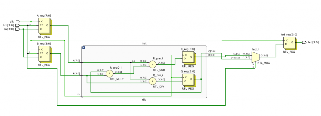
The first always block generates combinational logic only, doing all the computations of quotient and remainder. In this case, Q_pre and R_pre are fake registers, as the compiler does not infer any flop for those variables. The next always, a sequential one, is doing nothing else than transferring the result into the output 4bit registers synchronously with the rising edge of the clk signal. As you can see, there is no reset signal.
This can produce a glitchy blink of the output LEDs at power-on, but this is not visible for humans.
module div( input  clk,
            input  [7:0] A,
            input  [3:0] B,
            output reg [3:0] Q,
            output reg [3:0] R
          );

reg [3:0] Q_pre;
reg [3:0] R_pre;

always @*
begin
    Q_pre = A / B;
    R_pre = A - Q * B;
end

always @(posedge clk)
begin
    Q <= Q_pre;
    R <= R_pre;
end

endmodule
The top module, especially created for the Zybo is interfacing the four on-off switches, the four push-buttons and the four LEDs to the division module.
module top( input clk,
            output reg [3:0] led,
            input  [3:0] btn,
            input  [3:0] sw );


 reg [7:0] A;
 reg [3:0] B;
wire [3:0] Q;
wire [3:0] R;

div inst( .clk(clk),
          .A(A),
          .B(B),
          .Q(Q),
          .R(R)
         );

always @(posedge clk)
begin
    if(btn[3]) A[7:4] <= sw[3:0];
    if(btn[2]) A[3:0] <= sw[3:0];
    if(btn[1]) B[3:0] <= sw[3:0];
    if(btn[0]) led[3:0] <= R[3:0];
    else       led[3:0] <= Q[3:0];
end

endmodule
An on-board oscillator is producing the 125MHz clock signal.
Before synthesis, you may see the elaborated design, that looks like this:

The project is on the github.


No Responses