
Yet Another Switch Mode Power Supply Conversion

DIY Switch-mode Constant Current Supply
So, this is the story: I needed a some 1A+ current source, maybe 1.5A, for sure no more than 2Amps.
You will suggest that I can use a bench power supply in current limited mode. But the top-bench supplies are heavy and expensive. Furthermore, I do not want to carry it on the field, against elements and mostly I do not want to leave it unattended.
Research
I started searching for alternatives, knowing that computer power supplies are cheap, light and available. So why not convert one of those to a current source? Shouldn’t be that hard.

On the plus side, the computer power supply has a 5V standby that I can use to power additional circuitry. How about dropping an Arduino with a small display on it?!! Maybe later.
For now, I begin looking for power supplies schematics. Found someone else doing a conversion with adjustable voltage and current, then made a plan for changing the TL494 circuitry…
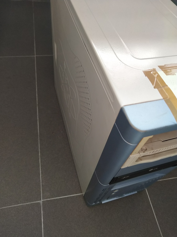
Next, I found an old computer case:
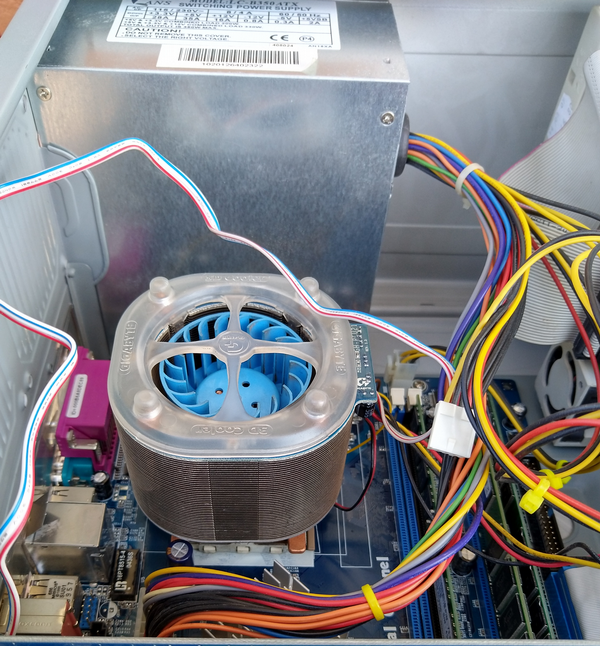
scavenged out the supply,
Started by cleaning up the supply unit, stripped the wires to work easily and … got a surprise: no 494. The unit has in its center some DIP16 chip marked 2003:
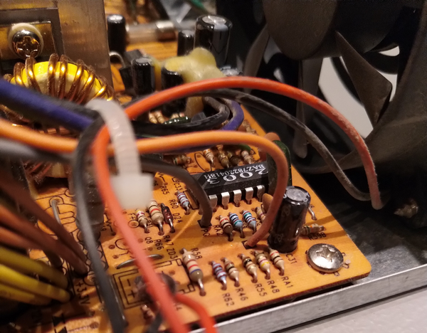
No problem, easy thing: I’ll find the datasheet and design a new conversion …
No such luck. Could not find a datasheet for the 2003 on the internet. Got frustrated and turned to another power supply unit I had laying around, hoping that the new one is based on the 494. I opened the unit, it was 494, so far so good. Some smoked traces reminded me why I had it unused … also it seemed I used it as a components source, so … I got more frustrated.
Forums experience
Went back to the internet for help and found some dirt cheap old power supplies for sale and some other guys modding ATX supplies.
Now, buying looks like a defeat, so I decided to postpone it and search someone else’s conversion to constant current (2003 chip in focus of course).
The mighty internet provided 2 types of solutions:
- “You can arrange an LM317 in a constant current configuration.” – not a fan because of the poor efficiency
- “I don’t advise playing around with these 400 watt power supplies unless you definitely know what you’re doing… John.” – definitively not a fan, also not sure about what i was doing…

Thanking John for his advice, I moved to non English search results.
Evrika moment
And I found a DIY article on diodnik.com: some guy modified an SMPS based on the 2003 chip and was kind enough to share details.
Thank you guy that forgot to sign your work.
It was a great moment, an evrika moment. Finally there was hope, a light rising above the horizon. Happiness was doubled by the excitement of a web page with English language option that keeps the Russian text on display. It is just like in the movies when all the Russians speak English with accent, only that this time was the other way around.

I translated the article with the help of my most of the time sometimes retarded friend: translate.google.com
Here is the result: original 2003 translated.pdf
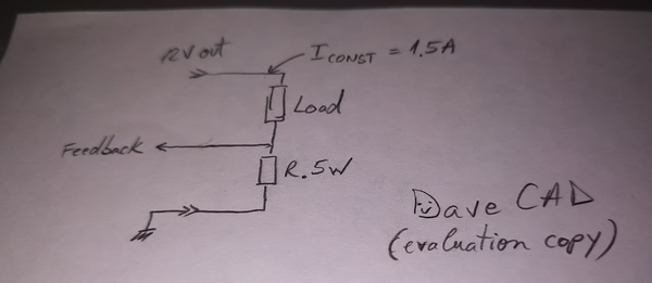
Translation done, now I am back to my project… started the CAD software and I draw some schematic:
After that I ordered some components, then I realized there is a situation where things can go wrong, really wrong: no load or Rload too big.
So I went imagining a solution for this new problem… Then ordered more components … Yes, at this time I also wondered if a lab power supply is really that expensive and yes I concluded that you can not put a price on fun, so funk the lab supply, I’ll modify the old junk.
Step 1
First step in modding is no mod. Just a simple test to see if I start from something functional: replace in capacitors that seemed to dry out (they looked surprisingly good compared to the mess on the board), powered up the supply and …. yes, of course the THR blew out … what is life without a little fun!?
Replacing the thermistor raised some questions:
- what thermistor was? (SCK 082) found something to replace it… sort of similar
- what cause the thermistor to fail? suspect number 1 : the new caps – look ok; next (I mean close near) are the diodes – look ok, took one out, measured ok and… I am dumb enough to not know the diode codes and curious enough to hit google with a question: LH 3A05. The result did not appeared straightforward but I found some info stating that it is a 3A @ 50V diode. I am ok with 3A but 50V???!!! so I went back ordering new components: P600K 6A @ 800V (it did not worked with whatever was mounted on it so I just took a bigger hammer)

(later edit) A friend told me he has a 2003 based ATX power supply and the diodes are LH4A05… so maybe the originals where not 50V. Please help if you have a datasheet…
I plugged in the board and measured the voltage on the caps: seemed right. Measured the auxiliary 5V … all good.
Step 2
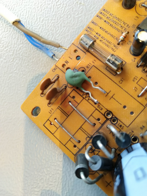
Let’s mod: first phase is cleaning the board of the unwanted components. This imply a huge risk of taking down useful components but it makes the schematic simpler, make some room on the board for the new parts needed for added functionality: one such example is the current measurement resistor that goes on the heat-sink in the space of a TO220 diode pair:

Here is the clean board:

Step 3
After the cleaning up, I started the 3rd step: faking the outputs. So, as indicated in the example 78L12 + 3 Rs. Again I was curious to see how the signal looks like… bad. Bad signal, bad news. There was a considerable amount of noise, going under 13V. So, quick fix: adding one diode and a capacitor.
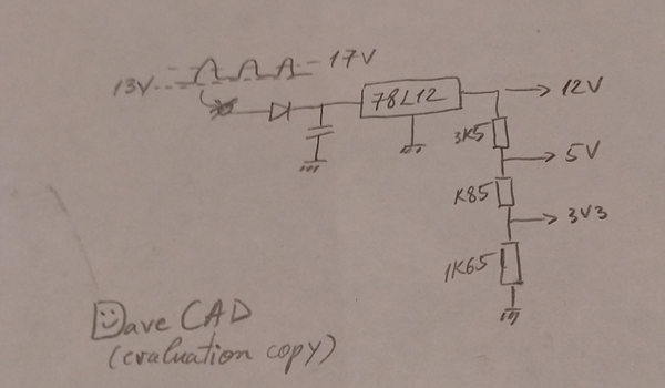
The first cap, some tens of nF, proved too small when network was connected to the 2003 chip so I digged out an old electrolytic 4.7uF … measured to be 7.8uF… ok, I’ll buy a new multimeter later. Now the voltage stays right and the cap stays in.
Step 4
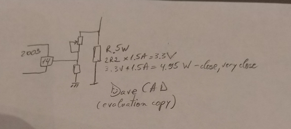
The feedback… let me present the schematic again:

I moved to a 2R2 resistor with more power (HS25 to be more precise), I reused R40 and I’ve added a 50K pot that went replacing R60. The pot was set for a 1.7A target value of the delivered current.

Step 5
The last mod: over voltage protection. Why? Remember the imaginary situation of no load or Rload too big? In this case, the output voltage will rise above the 16V of the filtering cap of the former 12V output line. And this is not good for the output cap and diodes.
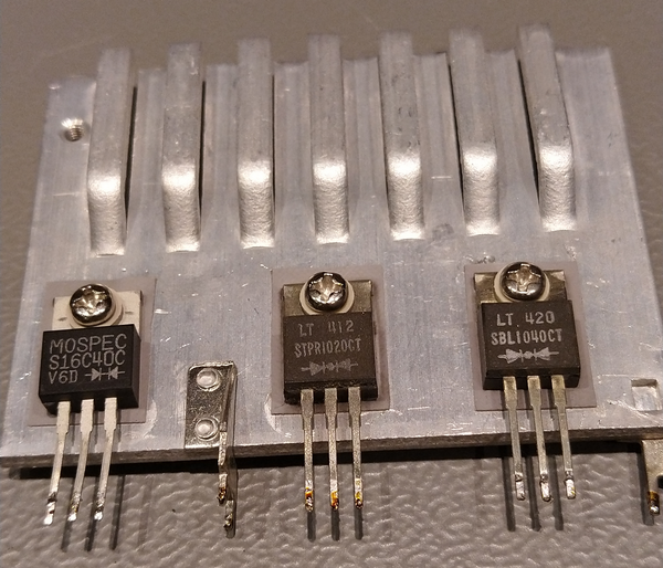
According to ST, the diodes are STPR1020 rated to 200V, so those remain there, and I replaced the original 16V capacitor with a 35V rated one. This way we are safe away from the 25V max that I expect from the supply.

The protection will use the monitoring capabilities of the 2003. For that, I plan to inject part of the output voltage over the 12V on the pin 6 making it rise above the nominal value and so triggering the stop of the supply. Let us see a schematic for this:

With equal Rs the protection will trigger at 2x(12V+0.7) = 25.5V. This is a bit too high… Plus we need to keep track of the 6k equivalent resistance of the voltage divider used to fake 5V and 3V3. For 1k3 and 2k2 pair the alarm should sound at around 24V output voltage. However, the value will be a bit different because of the current that will go into the 2003’s inputs and resistors tolerances. I apologize for not having images from this stage of the mod, I was caught in the process and I forgot to take pictures.
Testing the protection
Now let’s test it: multimeter on Amps in series with the 4R7 dummy load, power on… and all went ok. The new supply is delivering 1.7A.
Will the protection work? Test it by decoupling one of the multimeter leads and… no. The output voltage goes to 29V and stays there. Something went wrong… yes, I missed the internal output load of the 78L12:

Now, how to fix it!? Trial and error. I took out the 1k5 resistor, replaced it with a 1k pot that I did not connect to the output voltage but to my lab supply. The procedure looks like this: I start the modified power supply with the 4R7 load, then I connect the lab supply to the pot input and rise the voltage until the over-voltage protection kicks in; then modify the pot value and restart the procedure.
After that, I tuned the value of the potentiometer until I was happy with the voltage that triggered the protection then I removed the pot, I measured its value so I could replace it with some fixed values resistors.
The new modified computer SMPS is now passing the over-voltage test. All seems to work.
JOB DONE !!
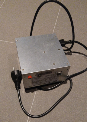
Now, this is how the modification looks like:


DIY Switch-mode Constant Current Supply – the end.
Later edit: it looks that Taiwan Semi produces 2A05 diodes rated 2A@600V. Are the 3A05 and 4A05 both on the 600V segment?
Later later edit: it also looks that Taiwan Semi produces 6A05 diodes rated 6A@50V? Me, I give up. If someone has a datasheet for the 3A05 found in the SMPS please share the info.

These things are basically built down to a price.
I had a few of these power supplies laying around and decided to convert them into something a little bit more useful, and I thought: “How about a +/-35V SMPS? I should be able to use that in an audio amplifier” and for the 400W power output, that would simply be excellent.
A wound toroidal transformer will be in excess of $50 if not more, while the smps is almost free (you can find them anywhere, really) . I started rewinding the main transformer(getting rid of all the other windings, and wind some thicker gauge wire according to some calculations).
The primary stage should be left in place, as there should be no modifications needed but the secondary should be stripped completely. I ran into a problem of not finding common anode diodes in the to220 package, especially for the power output that I would need.
Ok, I used some heavy duty schottky diodes that I had, and that solved the problem. Ok, it came the moment to modify the feedback loop.
The 2003 chip has multiple voltage monitoring rails and fooling them would be a hell of a nightmare…I made lots of voltage dividers (got some pots because I was too lazy) and after fine tuning them, gave it a shot. Then the ubiquitous 2003 chip did absolutely nothing.
I don’t really know if the chip is dead but without a datasheet on hand, that would be a pain in the a** to teoubleshoot. Got angry and desoldered the transformer and put it in another smps with a chip that I can get my hands into a datasheet, and work from there. Btw, most of these cheap atx smps do share similar parts, such as the main transformer.
So far I desoldered the unnecessary parts from the new board and resoldered the new transformer. It is quite hard to debug these things without proper isolated probes and experience, you’ll be looking at trial and error, which is not the best way to tackle such work.
This is my experience so far with these pesky power supplies. Maybe I’ll get on it again someday, but so far it’s gathering dust 🙂
Great work! Nice to hear that someone else struggled with the 2003 chip.
Good luck! Keep an eye on this page, nice things will come soon.
I really like what you guys are usually up too. This sort of
clever work and coverage! Keep up the excellent work guys.