
Bare Metal STM32 Programming – LED Blink
Do you want to start STM32 programming? Get the Blue Pill which is featuring the powerful & cheap ARM Cortex-M3 32-bit microcontroller then, let’s go!

We are going to build a LED blink app from scratch, using only the manual of the STM32F103C8T6 chip. The host platform used for this guide is Linux Mint 19.3. You can use as well, Ubuntu, Raspbian, and even Microsoft Windows.
Prerequisites
The hardware: the blue pill and for uploading the firmware we need at least a ST-Link v2 device.
The software: need to have installed the ST-Link tool and the cross compiler.
Prior knowledge: basic Linux operation, not being afraid of command line, C language, basic embedded stuff.
Steps to do
- We create in the same directory four files named:
- main.c
- linker.ld
- crt.s
- makefile
- Make a test build
- Connect the ST-Link
- Explain the schematic and documentation
- Write the code in main.c
- registers and bits definitions
- infinite loop that turns on and off the LED
- Build and upload to the board
Dummy main.c
void main (void)
{
    while (1);
}
For now it is just an infinite loop that does nothing.
C run-time assembly file crt.s
.cpu cortex-m3
.thumb

// end of 20K RAM
.word 0x20005000
.word _reset
.thumb_func
_reset:
    bl main
    b .
If you are not familiar with the ARM/thumb assembly and you don’t want to be, just skip the explanations below.
The first two lines are instructing the assembler to generate thumb code for the Cortex-M3 core. The thumb code is more compact in terms of memory footprint, but is a bit slower at run time. The value written at first .word line will be placed at the very beginning of the binary file at address 0x0000_0000 and represents the end of RAM. The second .word line is the reset vector and is placed at 0x0000_0004. The .thumb_func directive instructs the assembler to generate a thumb executable code from the subsequent lines. The last two lines are the jump to main() and the infinite loop, in case someone wants to exit from the main function.
Linker script file linker.ld
MEMORY
{
  FLASH (rx) : ORIGIN = 0x08000000, LENGTH = 64K
  RAM (xrw)  : ORIGIN = 0x20000000, LENGTH = 20K
}
This instructs the linker how to place different sections of data into the binary. It usually refers to ROM/FLASH and RAM. This data can be found in the datasheet at page 34.
Let’s build everything: makefile
CC = arm-none-eabi-gcc
AS = arm-none-eabi-as
LD = arm-none-eabi-ld
BIN = arm-none-eabi-objcopy
STL = st-flash
CFLAGS = -mthumb -mcpu=cortex-m3

all: app.bin

crt.o: crt.s
	$(AS) -o crt.o crt.s

main.o: main.c
	$(CC) $(CFLAGS) -c -o main.o main.c

app.elf: linker.ld crt.o main.o
	$(LD) -T linker.ld -o app.elf crt.o main.o

app.bin: app.elf
	$(BIN) -O binary app.elf app.bin

clean:
	rm -f *.o *.elf *.bin

flash: app.bin
	$(STL) write app.bin 0x8000000

erase:
	$(STL) erase
This makefile can be used for multiple things: for build, clean, upload or erase target. If you copy&paste the content from above, be careful at tab characters, could be replaced by spaces and make utility does not like this.
For build, cd to the files directory, then use any of these, there is no difference:
make
make all
When need the removal of the output files, use:
make clean
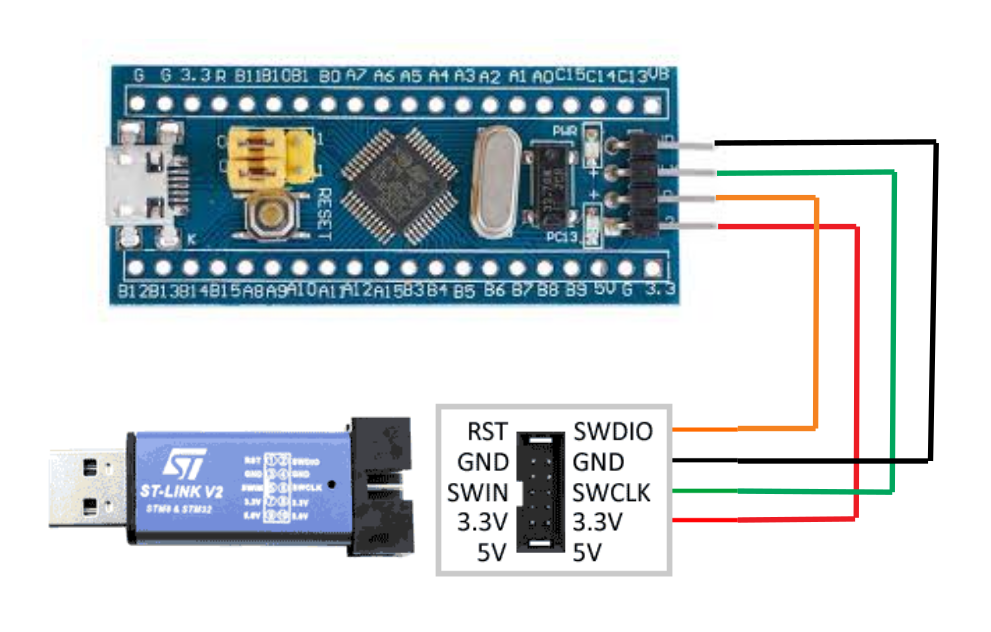
Connect the ST-Link v2
Before uploading the code into the board, you need to seat both jumpers towards the micro-USB connector, then connect the debugger to the Blue Pill like in the picture:
Caution! Do not use two USB connection at the same time (on debugger and on-board) because you risk to fry the board or PC’s USB ports. Disconnect one before plugging-in the other one.
For uploading the binary to the Blue Pill, respectively complete target erase, use either:
make flash
make erase
Let’s make the LED blinking
The Blue Pill has two LEDs, one for power and one driven by MCU, connected to port C, bit 13, as we can see in the schematic got from https://vcc-gnd.world.taobao.com/
Schematic and documentation
For making the LED to blink we need to configure GPIO port C13 and add some delay. We see in the schematic that LED turns on when GPIO pin is ‘0’ logic and turns off when ‘1’.
The real story is a bit longer, but I’ll tell you here the short version. To make a GPIO toggling in STM32, you need to work with two peripherals: RCC (reset and clock control) and GPIOx (general purpose input/output). The RCC is necessary because the GPIO has disabled clock by default.
In the STM32F10xxx reference manual at page 51 is the memory map, where we find out the GPIO Port C has the base address at 0x4001-1000 and the RCC is at 0x4002-1000.
First, we are going to activate the clock for GPIOC port. For that, we set bit IOPCEN in register RCC_APB2ENR (offset 0x18, bit 4).
Next, we need to configure the port C as push-pull output. We do this by writing into register GPIOC_CRH (offset 0x04), CNF = 0b00 (push-pull output) and MODE = 0b10 (low speed). Thus, for port C13 bits 23:20 are going to be set to 0x2.
The code
So, at the beginning of main.c let’s add the registers and bits definitions:
#include <stdint.h>

// register address
#define RCC_BASE      0x40021000
#define GPIOC_BASE    0x40011000

#define RCC_APB2ENR   *(volatile uint32_t *)(RCC_BASE   + 0x18)
#define GPIOC_CRH     *(volatile uint32_t *)(GPIOC_BASE + 0x04)
#define GPIOC_ODR     *(volatile uint32_t *)(GPIOC_BASE + 0x0C)

// bit fields
#define RCC_IOPCEN   (1<<4)
#define GPIOC13      (1UL<<13)
And finally, to turn ‘1’ and ‘0’ the pin we set/reset the bit 13 in GPIOC_ODR (at offset 0x0C). So, we replace the main() function in main.c:
void main(void)
{
	RCC_APB2ENR |= RCC_IOPCEN;
	GPIOC_CRH   &= 0xFF0FFFFF;
	GPIOC_CRH   |= 0x00200000;

	while(1)
	{
		GPIOC_ODR |=  GPIOC13;
		for (int i = 0; i < 500000; i++); // arbitrary delay
		GPIOC_ODR &= ~GPIOC13;
		for (int i = 0; i < 500000; i++); // arbitrary delay
	}
}
Build, upload & blink
Now, we build and flash the board:
make flash
After flashing is complete, if nothing happens, press the RESET button. The LED is blinking at ~1Hz.
If does not work, try cleaning up, erasing the target, then re-upload:
make clean
make erase
make flash
That’s all. You can find the code on github. Enjoy!


Excellent contribution
Thanks, Albert
Que bien; me sirvió mucho.
Y tienes más información o guías sobre programación bare metal STM32 ?
[translation]
How good; It helped me a lot.
And do you have more information or guides on STM32 bare metal programming?
Look on the front page, you will find more stuff. And more is yet to come soon.
Thanks! This is exactly what i was looking for.
Do you have to do anything special to include the standard peripheral library or can I just add it to the Makefile?
Yes you can add it to the makefile. I’m working on an example about that. Keep an eye on my blog.
Thanks!
I’m corean. sorry, just little english. your post is very help me.
55살에 시작하는 임베디드 배움이다.
너무 고맙습니다.
Glad to know that! Good luck and you are welcome back here!